Go to the previous chapter: Introduction
What is the breadboard terminology?
Almost all modern (full-size and half-size) breadboards have numerous holes, letters, numbers, and blue and red lines that give the breadboard its standard appearance. Here is the terminology you must know:
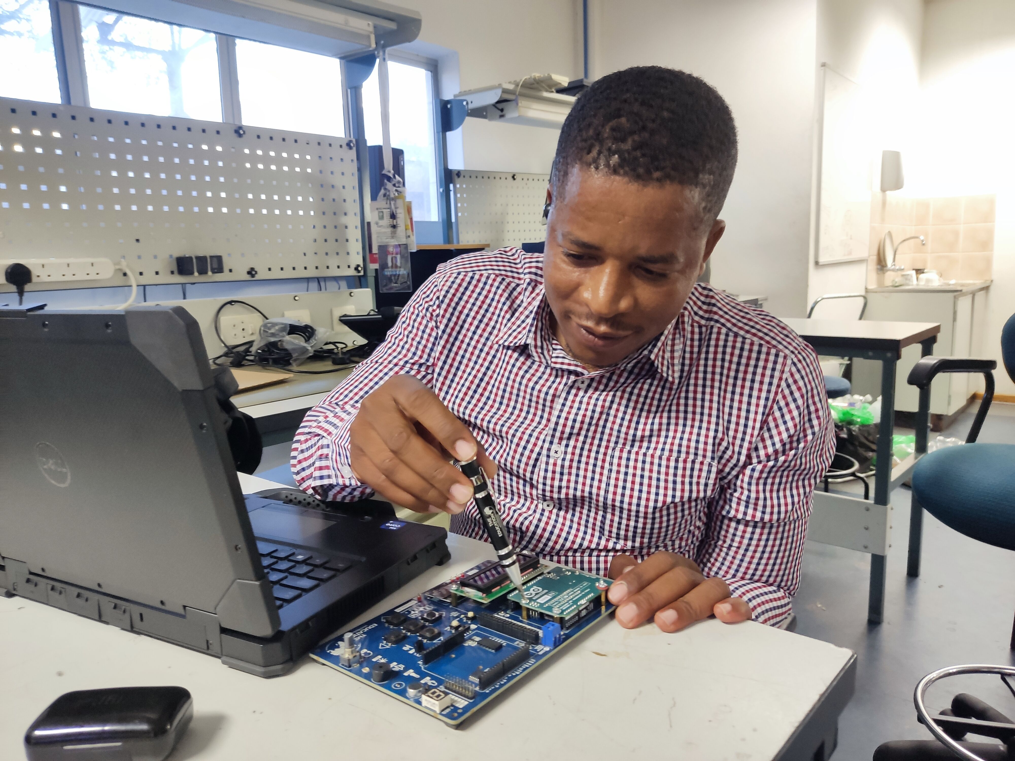
Letters
Printed at the top and bottom of the breadboard are letters from “A” to “J” running horizontally and dividing the holes evenly into vertical lines.
 |
Numbers
To identify horizontal rows, numbers from 1 to 30 are printed on left and right edges on half-size breadboards, and to 60 or 63 on full-size breadboards. Some breadboards use skip-counting in fives, but it doesn’t change the main concept of row-numbering on breadboards.
 |
Together, the numbers and letters guide you to locate a certain hole easily while building complicated circuits or during troubleshooting. For instance, hole “G15” is located at the intersection of column “G” and row “15.”
 |
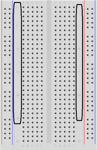
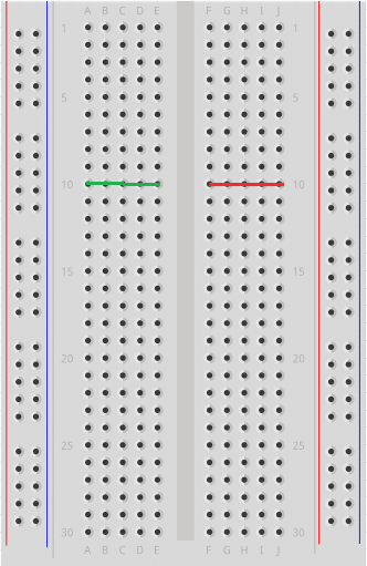
Horizontal Row
The rows or “Terminal strips” are where you are supposed to connect the electronic components. Rows are identified by numbers, and each row contains five holes on each side (left and right) separated by a middle divider. Every five holes in the same row are electrically connected, but they must be on the same side.
For example, in a row no. 10 the holes 10A, 10B, 10C, 10D and 10E are connected together, because they are in the same row on the same side. But they are not connected to holes F to J on the right side of the breadboard, because both sides are isolated by the middle divider.
 |
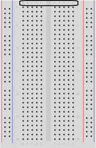
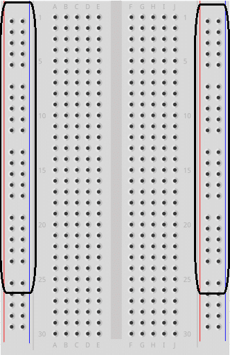
Vertical bus
This consists of two vertical columns that are commonly known as “Power rails.” Each breadboard contains two power rails located at the ends of both sides on the breadboard.
The purpose of the power rails is to connect the circuit to an external power supply. One column is to connect the circuit with the positive voltage (+) and the other column is to connect the circuit to ground (-).
 |
How to distinguish between positive voltage column and ground?
Positive voltage column:
- Located next to the red line
- Marked by a plus (+) sign (optional!)
- Ground column:
- Located next to the blue or black line
- Marked by a minus (-) sign (optional!)
Note that breadboards are available from different manufacturers. Some breadboards use colored lines to identify power rails, other breadboards use colored lines with plus (+) and minus (-) signs.
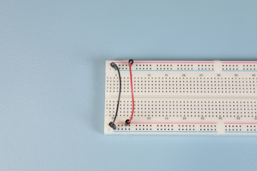
Tips! It’s good to notice that in some full-size breadboards the red and blue (or black) lines are broken in half, which means the upper half of the power rails is electrically isolated from the lower half to enable the use of one breadboard to connect two different circuits. If you wish to connect the two halves together, it’s enough to use jumper wires as shown below.
 |
Two halves of the breadboard are connected via red and blue jumper wires
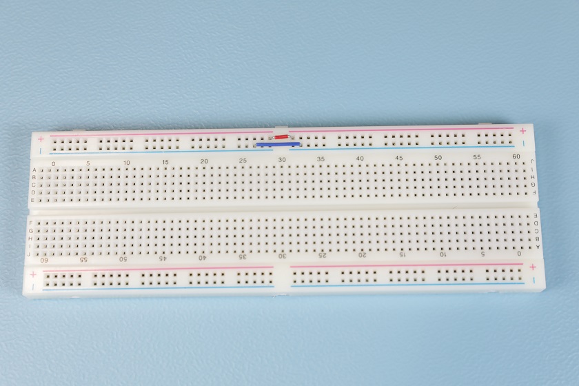
Tips! The power rails on the left side are isolated from the second set of power rails on the right side. Use jumper wires if you want positive voltage and ground to be available on both sides. (Remember to connect positive to positive and ground to ground.)
 |
Power rails from both sides are connected to each other via jumper wires
Central gutter
A middle divider or “ravine” that runs vertically and divides the breadboard symmetrically into left and right sides. As we mentioned earlier, the halves of the breadboard are electrically isolated from each other by the middle divider.
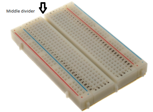 |
This ravine has very important functions:
-
It allows dual-in-line packages (DIPs) such as ICs to fit properly on the breadboard. As each pin of an IC serves a unique purpose, this ravine keep the pins isolated from each other to avoid short circuits.
-
It provides cooling for DIP components by allowing air to flow from beneath. ICs chip get warm under some circumstances.
Tips! Use an IC chip lifter or tweezers to remove ICs from the breadboard easily and safely.