Go to the previous chapter: Breadboard layout.
What’s inside the breadboard?
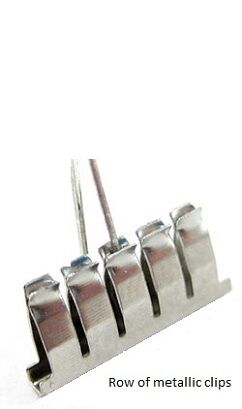
If your curiosity drives you to check what’s inside the breadboard, you will see rows of conductive metallic clips under the holes.
The clips have a spring-loaded feature that holds the leads of components firmly when you insert them into the holes.
Remember, every set of five holes in a row are electrically connected, because each metallic row contains five clips. Under each row of five holes there is a metallic row of five clips: one clip under each hole! That means if you insert any component into one of the five clips, the rest of the clip’s holes in the same row will be electrically connected to this component.
The power rails consist either of one long metal bar with many clips or two isolated bars in the case of breadboards where the upper half is isolated from the lower half.
Tips! As we mentioned, every set of five holes in the row are electrically connected by default; however, you can always connect other holes on the breadboard together by using a jumper wire, for example, or any other component such as a resistor.
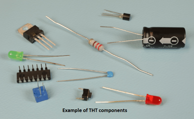
Which components are best to use with breadboards?
Having explained how breadboards work from the inside, it’s easy to guess which components are compatible with the breadboard.
Almost all components that have leads and are known as THT (through the hole technology) components can be used on breadboards. Since there is no need for soldering, we can connect the components simply by pushing the leads into the hole’s metal clips.
 |
 |
Tips! Some components do not have leads, such as variable resistors and DC motors, but you can still use them on the breadboard if you solder a wire to their terminals. Then you can use the wires as leads to be pushed into the holes.
How to build a circuit using a breadboard?
To build an electronic or electric circuit, it is highly recommended to follow a circuit schematic or diagram. The circuit schematic is a pictorial representation of the circuit connections and uses a special symbol for each component.
We will explain the circuit schematic in a separate tutorial, but we are going to use a simple example to learn how to build a circuit using the breadboard.
Attention! Before we convert the schematic into a real circuit, we must know the main purpose of the circuit and what results it should give.
Remember! When connecting the components to the breadboard we must focus on correct connection rather the location of the components in the schematic, because a real circuit on a breadboard always looks different than in the schematic.
So, let’s start.
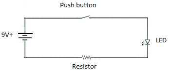 |
Given the schematic above, the circuit is intended to light the LED whenever the push button is pressed.
Steps:
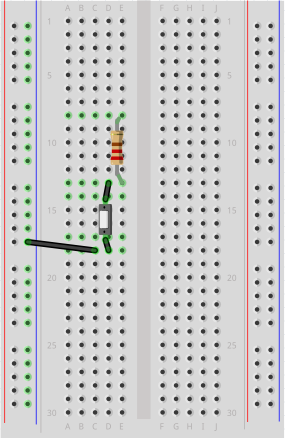
- Place the push button anywhere on the breadboard (do not put both leads on the same row). Connect it from one side to the ground bus (-) a via jumper wire.
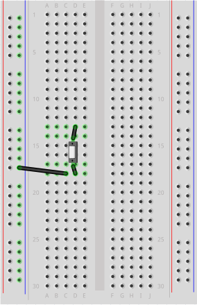 |
- Connect the other side of the push button directly to the resistor. “Directly” means there’s no need for jumper wire (remember that the five holes in the same row are connected by default).
 |
- Connect the negative lead (cathode) of the LED directly to the resistor
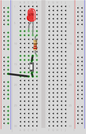 |
- Connect the positive lead (anode) of the LED to the positive bus (+) via a jumper wire.
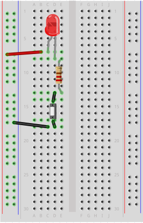 |
- Finally, connect the ground wire (-) from the power supply to the ground bus (-) on the breadboard, then connect the positive wire (+) from the power supply to the positive bus on the breadboard (+).
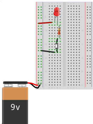 |
- Press the push button to test the circuit. The LED should light up. ENJOY your first circuit ????
If the circuit doesn’t work, check the connections carefully and follow the steps from the beginning.